






Thread rolling screws form internal threads by plastic displacement of the workpiece material rather than cutting, producing stronger, work-hardened threads in ductile metals such as aluminium, mild steel, and brass. No chip generation means cleaner assembly and reduced mating-hole wear. DIN 7500 defines the 30° wedge-form profile. Reusable and vibration-resistant, suited to high-volume automotive and electronics production. Metric M2.5–M10, case-hardened steel with zinc or phosphate finish.
Filter By
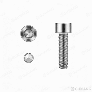


A thread rolling screw forms its own internal thread in a pre-drilled or cored pilot hole by displacing material—not by cutting it. The process produces no chips. The screw’s thread profile is shaped so that as it is driven, the material of the mating part cold-flows into the thread form around it.
The defining geometric feature is a trilobular cross-section—three lobes spaced 120° apart around the thread circumference. Only the lobe crests contact the pilot hole wall during forming. The valleys between lobes clear the hole, reducing driving torque and providing space for the displaced material to flow. This is not a round screw with an interference fit. It is a lobed screw with a deliberate forming geometry.
The screw enters a pilot hole whose diameter sits between the screw’s minor diameter and its effective forming diameter. As the first full thread engages, the lobe crests press into the hole wall. The material—aluminum, zinc die-cast, mild steel, or thermoplastic—deforms plastically, flowing into the thread valleys between the lobes.
The result is a zero-clearance internal thread. Unlike a cut thread that has a measurable gap between the fastener thread and the parent material thread, a rolled thread fills the space completely. This eliminates radial play and the micro-movement that loosens cut-thread joints under vibration.
The forming process work-hardens the parent material at the thread interface. In ductile metals like aluminum and low-carbon steel, the formed thread has higher hardness and higher ultimate strip-out torque than a cut thread of the same pitch in the same material. The screw itself is case-hardened to roughly surface hardness 450–550 HV to survive repeated forming cycles without thread deformation.
| Property | Thread Rolling Screw | Thread Cutting Screw |
|---|---|---|
| Debris | Zero chips | Produces chips that can short electronics or jam mechanisms |
| Blind holes | Safe—no chip evacuation needed | Requires chip clearance at the hole bottom; chips pack and hydrolock the screw |
| Strip-out torque | Higher in ductile materials due to work-hardening and full thread fill | Lower; the cut thread has clearance and a rougher surface finish |
| Material range | Ductile materials only—aluminum, zinc, mild steel, brass, thermoplastics | Brittle materials—cast iron, thermoset plastics, glass-filled nylon, magnesium |
| Driving torque | Higher during the forming phase (material displacement takes energy) | Lower overall (cutting removes material with less resistance) |
| Reusability | Limit roughly 3–5 insertions—each cycle cold-works the formed thread further | Roughly 5–10 insertions—the cut thread doesn’t change but wears with each pass |
| Hole tolerance | Critical—pilot hole diameter must match the screw specification | Forgiving—the cutting edge compensates for hole variation |
The material ductility constraint is the primary selection filter. Thread rolling screws need the parent material to flow. Cast iron doesn’t flow under this type of deformation; it crumbles. Glass-filled nylon at 30% fiber content fractures rather than yielding. If the material can’t yield plastically, the screw either strips the hole or snaps.
Thread rolling screws are available in the full range of machine screw head styles:
| Head Style | Use Case |
|---|---|
| Pan Head (DIN 7985 / ISO 7045) | General assembly, electronics enclosures |
| Flat Countersunk (DIN 7991 / ISO 10642) | Flush mounting on covers and panels |
| Hex Washer Head (DIN 6921) | High-torque driving into castings and extrusions |
| Button Head | Low-profile visible fasteners on consumer products |
| Truss Head | Spreading clamp load over thin sheet metal or plastic bosses |
Drive recesses follow the same pattern: Phillips (PH), Pozidriv (PZ), Torx (T), and hex socket are all available. Torx and hex socket are preferred for production—the higher driving torque of thread forming demands a drive that resists cam-out. Phillips and Pozidriv slip under the forming load if the operator isn’t perfectly aligned.
Case-Hardened Steel (Standard) The screw core is medium-carbon steel with a carburized or carbonitrided case. Surface hardness approximately 450–550 HV with a ductile core at roughly 300–400 HV. The hard case survives the forming torque without thread flattening; the ductile core prevents brittle fracture under over-torque. Typical strength class equivalent: 10.9 or higher depending on the heat treatment specification.
Stainless Steel Austenitic stainless (A2/A4, 304/316) thread rolling screws are available for corrosion-resistant assemblies. The forming performance is lower than case-hardened steel—stainless threads gall against aluminum and stainless parent materials if not lubricated. Specify a wax or polymer dry-film coating on stainless thread rolling screws heading into aluminum holes.
Zinc and Zinc Flake Coatings Zinc electroplating (5–8 µm) provides indoor corrosion resistance. Zinc flake coatings (8–15 µm) provide higher salt-spray life—roughly 240–720 hours to red rust per ISO 9227 depending on the flake system. For automotive under-hood and chassis applications, zinc flake with an integral lubricant topcoat reduces the forming torque and prevents hydrogen embrittlement in the hardened screw core.
PTFE and Dry-Film Lubricants A PTFE or molybdenum disulfide patch on the thread reduces the driving torque during forming by roughly 20–30%. This matters in production: on a line installing 12 thread rolling screws per assembly, the torque reduction translates directly to lower operator fatigue and faster cycle time.
| Standard | Scope | Thread Range | Notes |
|---|---|---|---|
| DIN 7500-1 | Thread rolling screws for metric ISO threads, coarse pitch | M2 to M10 | Standard forming lobe geometry, widely used in European automotive |
| DIN 7500-2 | Fine pitch variant | M4 to M12 | Higher vibration resistance, thinner-walled bosses |
| ISO 7085 | Equivalent to DIN 7500 with international adoption | M2 to M10 | Essentially the same screw with minor dimensional harmonization |
| Manufacturer-specific | Trilobular variants with optimized lobe geometry | M1.6 to M20 | Proprietary lobe profiles that reduce driving torque further |
The pilot hole diameter is the critical assembly parameter. DIN 7500 specifies a hole tolerance range for each thread size—too tight and the screw snaps during forming; too loose and the formed thread is shallow with low strip-out torque. For an M5 rolling screw, the recommended pilot hole is typically 4.5 mm in aluminum and 4.6 mm in steel—the forming lobe crest diameter is what matters.
Automotive Powertrain and Chassis Thread rolling screws assemble throttle bodies, valve covers, ABS modules, and steering-column housings. The chip-free process is mandatory—a stray metal chip in an engine oil gallery or ABS valve block destroys the component. Aluminum alloy die-castings (A380, A383, ADC12) form threads reliably with case-hardened screws. A zinc flake coating with integral lubricant handles the heat, oil, and salt exposure of under-hood service.
Consumer Electronics Smartphone frames, laptop chassis, and tablet housings in aluminum or magnesium alloy use thread rolling screws to eliminate chip contamination on PCB assemblies. A stray chip across a logic board trace shorts the device. Thread rolling screws in M1.6 to M2.5 with Torx drive are standard on high-end electronics where the assembly line runs at thousands of units per hour.
Appliance Manufacturing Washing machine tubs, refrigerator compressor mounts, and microwave cavity assemblies use thread rolling screws into zinc-plated steel brackets. The vibration resistance of a zero-clearance thread matters in appliances that spin, pump, or rattle for their entire service life. A cut thread in the same bracket can loosen within months; a rolled thread stays tight.
Plastic Boss Design Thread rolling screws for thermoplastics use a specialized thread profile—typically a 30° or 45° flank angle with a wide thread spacing. The pilot hole in the plastic boss is smaller than the screw major diameter, and the boss wall thickness must be at least 0.5× the screw diameter to resist hoop stress during forming. Common in power tool housings, automotive interior trim, and medical device enclosures.
| Decision | What to Ask | Guidance |
|---|---|---|
| 1. Parent material | Can it flow? | Ductile (aluminum, zinc, mild steel, brass, unfilled thermoplastics) → thread rolling. Brittle (cast iron, glass-filled polymer, magnesium) → thread cutting or machine screw with insert. |
| 2. Chip tolerance | Can the assembly accept debris? | Zero tolerance (electronics, hydraulics, engines) → thread rolling. Debris acceptable (structural steel, wood framing) → thread cutting is cheaper. |
| 3. Pilot hole control | Is the hole diameter tightly controlled? | Tight tolerance (drilled or reamed hole) → thread rolling works. Loose tolerance (as-cast hole, punched sheet) → thread cutting compensates for variation. |
| 4. Production volume | How many assemblies per day? | High volume—the tooling investment for controlled pilot holes pays back in assembly speed, chip elimination, and lower rework. Low volume—thread cutting may be simpler to implement. |
| 5. Reusability | How many assembly cycles? | 3–5 insertions maximum for thread rolling in aluminum. Specify a helical insert for high-cycle service and use a standard machine screw into the insert. |
Can thread rolling screws be used in steel? Yes—in low-carbon mild steel up to roughly 150 HB hardness. The screw must be case-hardened and the pilot hole must be precise. Above 150 HB, the material resists plastic flow and the screw strips or snaps. For higher-hardness steel, use a thread-cutting screw or tap the hole conventionally.
What happens if the pilot hole is too small? The screw snaps during forming. The forming torque spikes beyond the screw’s torsional strength. This is the most common assembly failure with thread rolling screws. Check the pilot hole with a go/no-go gauge before running production.
Do thread rolling screws work in stainless steel parent material? Only with a lubricant coating on the screw and a pilot hole at the upper end of the tolerance range. Stainless-on-stainless forming galls aggressively. Specify a wax or PTFE dry-film coating. Test extensively before committing to production.
How is the pilot hole diameter determined? The screw manufacturer publishes a recommended hole diameter for each thread size and parent material. For DIN 7500 screws, the hole is typically 0.1–0.3 mm smaller than the screw major diameter in aluminum and 0.05–0.15 mm smaller in steel. Never use the minor diameter as the pilot hole size.
Are thread rolling screws the same as self-tapping screws? Thread rolling screws are a type of self-tapping screw. The self-tapping category includes both thread-forming (rolling) and thread-cutting screws. When a specification says “self-tapping” without qualification, verify which type—they are not interchangeable.
What is the correct driving speed for thread rolling screws? Approximately 500–2,000 RPM depending on thread size. Smaller screws (M2–M3) run faster. Larger screws (M6–M10) run slower to control heat buildup during forming. Speed matters: too fast and the parent material work-hardens before the thread fully forms, increasing the risk of strip-out.
Social Chat is free, download and try it now here!