





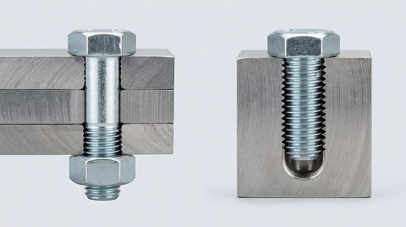
A bolt and a screw are both externally threaded fasteners, and the practical difference between them is how each one is used, not how it looks. A bolt is inserted through clearance holes in the parts being joined and is tightened with a nut, while a screw mates with an internal thread already cut into one of the parts, or cuts its own thread as it is driven. That single distinction drives the rest of the conversation: whether the joint is clamped from the nut side or the head side, whether a tapped hole is required, how torque gets into the fastener, and which standard families apply. Buyers and engineers who mix up the two end up with the wrong hole preparation, the wrong torque tooling, or the wrong grade callout, and the error usually shows up on the assembly line rather than on the drawing. This guide walks through the definition, the engineering standards, the type families, size notation, strength grades, and selection logic, and closes with the manufacturing services that turn a specification into a production fastener.
he Short Answer: What Separates a Bolt from a Screw
State the rule once and the rest of the subject falls into place: a bolt works with a nut, and a screw works without one. In a bolted joint, the bolt passes through clearance holes in two or more stacked parts and a nut is threaded onto the far end. Tightening the nut stretches the bolt shank in tension, and that tension clamps the stack so that friction between the parts carries the service load. In a screwed joint, the screw is turned directly into a tapped hole in one of the parts, or into a material that the screw thread cuts or forms for itself, and the head drives the screw. There is no nut on the far side because the mating thread lives in the workpiece.
This rule is a service classification, not a shape classification. The same external thread form, the same head style, and the same nominal diameter can appear on a part that one catalog calls a bolt and another catalog calls a screw. What changes is the joint the part is intended for. The ASME inch-series standards draw exactly this line: ASME B18.2.1 defines a bolt as a fastener intended to be tightened by torquing a nut, and ASME B18.6.3 defines a machine screw as a fastener intended to be tightened by torquing its head into a tapped hole [3]. Engineers use the same logic every day on the shop floor, which is why a 1/2-13 hex part becomes a “hex bolt” when it clamps a flange with a nut, and the identical thread becomes a “cap screw” when it threads into a blind tapped hole in a housing.
The distinction matters commercially for three reasons. First, hole preparation differs: a bolted joint uses oversized clearance holes and does not need a tapped hole, while a screwed joint needs a tapped hole or a self-tapping point. Second, torque tooling differs: the nut side and the head side have different access requirements, and some bolted joints are tightened with the head held and the nut turned, which flips the tooling arrangement. Third, removal behavior differs: a bolt can be removed by pulling the nut, but a screw that has cut its own thread in soft material can damage the thread on the way out. None of that shows up in a photograph of the two parts side by side, which is exactly why the “how it is used” rule beats the “how it looks” rule in every engineering discussion.
Core Differences at a Glance
The table below compresses the comparison that the rest of the guide expands. Each row is a practical decision point that appears on drawings, in purchasing requests, and on the assembly line.
| Comparison point | Bolt | Screw |
|---|---|---|
| Mating part | Nut on the far side of the joint | Tapped hole in a component, or a thread cut into the material |
| Hole preparation | Clearance holes in all stacked parts | Tapped hole, pilot hole, or direct self-tapping drive |
| Torque application | Usually on the nut; sometimes the head is held while the nut turns | On the head, through the drive recess or wrenching flats |
| Thread duty | Thread engages the nut or a tapped hole; full and uniform for most of the length | Thread engages a tapped hole, or is hardened and sharp enough to cut its own thread |
| Removal | Nut comes off and the bolt is reused; joint is cleanly serviceable | Unscrewed from the hole; self-cut threads can strip or gall in soft materials |
| Load path | Clamp load from bolt stretch; shear carried by friction between clamped parts | Clamp load from thread engagement; lighter-duty assemblies dominate |
| Typical standards | ISO 898-1, ASME B18.2.1, ASTM A307, ASTM F3125 | ASME B18.6.3, ISO 965-1, ISO 3506 |
| Common head styles | Hex, carriage, flange, eye, T-head, socket cap | Machine, wood, self-tapping, self-drilling, set, drywall, socket cap |
Read the third row carefully because it catches the most people. A bolt can be tightened either by turning the nut or by turning the head while the nut is held, and the joint is dimensioned from the nut side. A screw is always driven from the head side, and the joint is dimensioned from the head to the thread tip. When a designer calls out a “bolt” but specifies a blind tapped hole, or calls out a “screw” but adds a nut to the drawing, the assembly either will not fit or will be assembled with the wrong torque path.
Two more mechanical facts belong in the quick view. First, the thread engagement length rule of thumb applies differently. A screw into a tapped hole needs roughly one times the diameter of engagement in steel and more in softer materials, while a bolt with a nut depends on the nut height plus the thread protrusion beyond the nut. Second, the torque source changes the way preload is controlled: a bolted joint often relies on torque-to-yield or angle-controlled tightening on the nut, while a screwed joint usually relies on head torque alone, which makes friction on the threads and under the head a bigger factor in the final clamp load.
Engineering Definitions: What ISO and ASME Actually Say
The everyday rule maps cleanly onto the standards used in global fastener procurement, and knowing the exact wording prevents the classic misquote that “a bolt has a partially threaded shank and a screw is fully threaded.” That visual shortcut is wrong on both sides of the ledger. The governing documents sort fasteners by service intent.
ISO 898-1, the international standard for mechanical properties of fasteners made of carbon steel and alloy steel, covers “bolts, screws and studs” as one family and grades them by property class, from 4.6 up to 12.9. The standard does not draw the bolt-screw line by geometry; it sets the strength, hardness, and ductility requirements that a fastener must meet regardless of the word used on the drawing [1]. The line between bolt and screw in the ISO world is drawn by the design intent in the joint: the same property class applies whether the part engages a nut or a tapped hole, and the callout must name the thread form and length correctly for the mating part.
ASME B18.2.1 covers inch-series square and hex bolts and screws. Its bolt definition centers on the nut: a bolt is an externally threaded fastener inserted through holes in assembled parts and normally tightened or released by torquing a nut. ASME B18.6.3 covers inch-series machine screws and tapping screws, and its machine screw definition centers on the tapped hole: a machine screw is an externally threaded fastener that is assembled into a tapped hole and is tightened by torquing the head [3]. That is the formal pair that the everyday rule paraphrases, and it is also why the same physical part can carry either name.
ASME B18.2.8, the inch-series “slow-bolt” guide, and the related B18 family documents add another layer: they list bolts, cap screws, machine screws, and studs as separate categories with separate dimensional and application notes. The terminology differences show up in practice in four ways worth memorizing.
| Naming question | Standard answer | Why it matters |
|---|---|---|
| Hex bolt vs hex cap screw | B18.2.1: bolt for nut joints; cap screw for tapped-hole joints | Identical threads, different joint intent and tolerance conventions |
| Machine screw vs bolt | B18.6.3: screw engages a tapped hole and is head-driven | Drives the tapped-hole callout and the tapping operation |
| Lag bolt vs lag screw | Lag screw by function: it cuts its own thread in wood | The “bolt” name is a trades term; the engineering behavior is a screw |
| Carriage bolt vs coach bolt | Same part, regional naming; always nut-driven | No tapping, no pilot hole beyond the clearance hole |
ASTM A307 covers low-carbon steel bolts, studs, and threaded rod in inch series, and ASTM F3125 covers high-strength structural bolts (including the former A325 and A490 grades) for structural steel joints 4. These standards sit above the dimensional standards: they set the material, tensile, and yield requirements for a specific duty, and they frequently override the generic property class in structural work. A structural bolted joint under F3125 is a nut joint by definition, because the connection is a clearance-hole, high-preload design tightened to the fastener’s proof load.
The full landscape of dimensional and material standards, including where DIN, ISO, ANSI, and ASME documents overlap, is laid out in our fastener standards guide. For this article the operational summary is short: when a part works with a nut, call it a bolt and specify it under the bolt standards; when it threads into a workpiece, call it a screw and specify it under the screw standards.
Bolt Types and Their Jobs
Bolts are the workhorses of structural and machinery connections because a nut joint can be disassembled, re-tensioned, and inspected without destroying anything. Each bolt type changes the head geometry, the bearing arrangement, or the intended loading mode, and the differences decide tooling, hole size, and torque limits.
Hex bolts and hex cap screws. The six-sided head is the default because a wrench or socket grips it from the side with almost no slip, and the head height and bearing area are generous enough for heavy clamp loads. In inch-series practice the name splits by duty: a hex bolt for nut joints and a hex cap screw for tapped-hole joints, with the cap screw carrying tighter tolerances on the head and fillet. Metric practice tends to call the same geometry a hex bolt (ISO 4014/4017) regardless of joint type, which is why the drawing callout, not the catalog name, carries the authority. The full family is covered in our hex bolts guide with grade and size tables.
Carriage bolts. A carriage bolt has a round head and a square neck under the head. The square neck bites into the material as the nut is tightened, so the head side never needs a wrench: the bolt cannot rotate while the nut is driven. That makes carriage bolts the standard choice for wood-to-wood and wood-to-steel connections in fencing, decking, and timber framing, where only one side of the joint is accessible.
Eye bolts. The head is a closed loop instead of a hex, and the threaded shank anchors into a plate, a beam, or a tapped block. Eye bolts carry lifting and rigging loads, and the grade matters enormously: a forged eye bolt rated for overhead lifting has a marked working load limit, while a generic bent-wire eye bolt is not a lifting component at all. The thread and the eye plane must be matched to the load direction, because side loading derates the capacity.
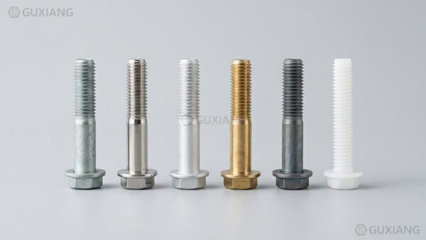
Flange bolts. A flange bolt replaces the separate washer with an integral circular bearing face under the head. The flange spreads the clamp load over a larger area and can eliminate a loose washer from the BOM, which is why flange bolts dominate automotive engine and chassis joints where package space is tight and the joint must not relax. Serrated flange bolts add small teeth under the flange that bite into the surface and resist loosening under vibration.
T-head bolts. The head is a rectangular or square block that slides into a T-slot in a machine table or a casting. Tightening the nut pulls the head against the slot shoulder, which locks the bolt in position along the slot. T-head bolts are the standard way to clamp workpieces and fixtures to milling machine tables and transfer lines, and the head width must match the slot width exactly or the clamp will not hold.
Structural bolts. These are the highest-duty members of the bolt family: ASTM F3125 Grade A325 and A490 in inch series, and property class 8.8 or 10.9 equivalents in metric work. Structural bolts carry the shear and tension loads of steel building frames and bridges through friction-type or bearing-type connections, and their installation is controlled by a torque or turn-of-nut procedure rather than a hand torque. Mixing a Grade 2 bolt into a structural connection is a safety defect, not a sourcing choice.
Anchor bolts. Anchor bolts embed into concrete foundations and stick out to receive a base plate, a column, or a piece of machinery. The embedded end uses a hook, a plate, or a forged head to develop pull-out resistance, while the exposed threaded end takes the nut that clamps the structure down. Anchor bolt placement is fixed at pouring time, so the projecting thread length and the template accuracy are the two details that get checked first on every foundation job.
| Bolt type | Head / feature | Typical joint | Primary load | Tooling |
|---|---|---|---|---|
| Hex bolt | Six-sided head | Flanges, frames, machinery | Tension preload | Socket or wrench on nut |
| Carriage bolt | Round head + square neck | Wood and timber connections | Clamp load, shear | Wrench on nut only |
| Eye bolt | Closed loop head | Lifting and rigging | Direct tension | Shackle or hook |
| Flange bolt | Integral bearing face | Automotive, compact machinery | Tension preload | Socket on head or nut |
| T-head bolt | Rectangular T-slot head | Machine tables, fixtures | Clamp load | Wrench on nut |
| Structural bolt | Heavy hex head | Steel frames and bridges | Tension and shear | Turn-of-nut or torque wrench |
| Anchor bolt | Hook, plate, or forged head | Foundations, base plates | Tension, pull-out | Wrench on exposed nut |
Choosing among these starts with the load path, not the head style. A lifting application wants a certified eye bolt; a timber fence wants a carriage bolt; a structural frame wants a specified structural bolt. When the head style is still open after the load is fixed, the head shape and drive become packaging and tooling questions, and the answer usually follows the assembly access.
Screw Types and Their Jobs
Screws carry the same threading, clamping logic into joints where there is no nut and no access to the far side. The screw family is wide because the point, the thread form, and the hardness have to match the material being fastened, and the type names encode that match.
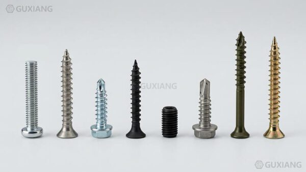
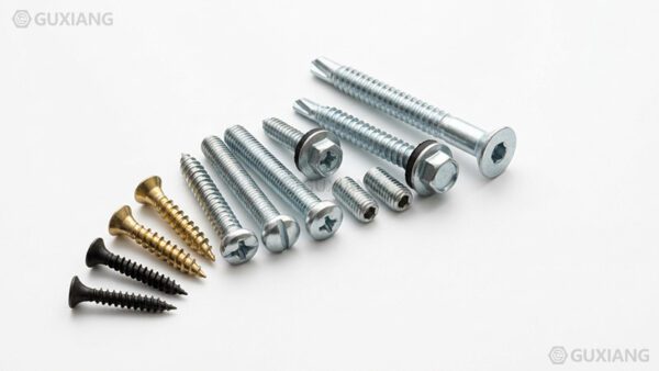
Machine screws. A machine screw is the direct counterpart of a bolt in a tapped hole: it engages an internal thread cut into a component and is driven from the head. Machine screws come in diameters from tiny instrument sizes up to about 1/2 inch, with either coarse or fine threads, and they are specified in the same callout language as bolts: diameter, thread, length, head style, drive, material, and finish. The size conventions, including the distinction between number sizes and fractional sizes, sit in our machine screw size chart.
Socket head cap screws. These are machine screws with a cylindrical head and a hex socket drive. The socket drive transfers torque with almost no cam-out, the low-profile head fits into counterbored holes for flush assembly, and the strength is typically high because the head design allows heat-treated alloy steel at 12.9 or Grade 8 levels. Socket head cap screws are the default for tooling, die sets, machine guards, and any joint that is tightened and released repeatedly.
Wood screws. A wood screw has a sharp gimlet point and a thread that cuts into wood grain, pulling the screw into the material without a nut. The thread usually stops below the head on the unthreaded shank, so the clamping action comes from the shank being pulled into the top board while the head presses it down. Pilot hole practice decides most of the performance: hardwoods need a drilled pilot and a countersink, while softwoods can take a direct drive, and the drilling rules follow the species hardness and the screw diameter.
Self-tapping screws. The thread form on a self-tapping screw cuts or forms a mating thread in the material as the screw drives in. Sheet metal screws are the most common family: they tap into thin steel, aluminium, and plastic sheet without a pre-tapped hole. The point style decides the mechanism: a sharp point cuts a thread in ductile metal, while thread-forming points push the material aside and work best in plastics. Self-tapping screws save one operation per joint, which is why they dominate enclosures, ductwork, and HVAC.
Self-drilling screws. A self-drilling screw carries a drill-point tip ahead of the thread, so one screw drills its own hole and then taps its own thread in a single drive. The tip looks like a tiny twist drill and must be long enough to pass through the material stack before the thread starts cutting. Self-drilling screws are the production answer for steel-to-steel and steel-to-wood fastening in metal buildings and roofing, because the crew eliminates the separate drilling step entirely.
Set screws. A set screw is headless, usually with a socket drive, and it is threaded into a tapped hole in a hub or collar to press against a shaft. Set screws lock pulleys, gears, and handles to shafts by friction or by embedding a cone or cup point into the shaft. The holding power depends on the point style, the hardness, and whether a flat is ground into the shaft, and the shaft penetration limit is a standard engineering check.
Drywall screws. Drywall screws are hardened, self-tapping production screws with a bugle head, a needle point, and a double-lead thread tuned for gypsum board on wood or steel studs. They drive fast, countersink themselves below the paper face, and are available in coarse thread for wood studs and fine thread for steel studs. Their coating is typically phosphate or a corrosion-resistant finish selected for the exposure class of the framing system.
Cap screws and shoulder screws. The “cap screw” family in inch-series practice (B18.3 for socket cap screws, B18.6.3 for slotted and recessed cap screws) covers headed screws that are tightened by the head into tapped holes. Shoulder screws add a precision ground shoulder between the head and the thread, so the shoulder acts as a bearing surface or a pivot pin while the threaded end clamps. Shoulder screws are common in linkages, hinges, and locating pins.
| Screw type | Point / thread | Typical material | Pre-drill needed | Drive access |
|---|---|---|---|---|
| Machine screw | Uniform thread, blunt or pointed end | Tapped holes in metal and plastic | Tapped hole | Head, any drive |
| Socket head cap screw | High-strength, cylindrical head | Tooling, machine assemblies | Tapped hole or counterbore | Hex socket |
| Wood screw | Sharp gimlet point, tapered thread | Wood and soft materials | Pilot in hardwood | Head, slotted or Phillips |
| Self-tapping screw | Cutting or forming thread | Sheet metal, plastic, thin steel | Usually none | Head |
| Self-drilling screw | Drill point ahead of thread | Steel-to-steel, metal buildings | None | Head, hex or Phillips |
| Set screw | Headless, point styles | Hubs on shafts | Tapped hole | Hex socket |
| Drywall screw | Needle point, double lead | Gypsum board on studs | None | Head, Phillips |
| Shoulder screw | Ground shoulder + thread | Linkages, pivots, locating pins | Tapped hole + clearance | Head, socket |
The screw family overview, with the full taxonomy and selection logic across all of these types, lives in our types of screws industrial guide. Head and drive geometry is a separate axis, and the practical differences between Phillips, Torx, slotted, hex, and square drives are covered in the screw head types guide.
Sizes and Naming: Reading a Bolt or Screw Callout
The size system is where bolt and screw practice diverges most visibly, and where the naming difference between metric and inch series causes the most rework. Every callout carries four pieces of information: nominal diameter, thread pitch or threads per inch, length, and strength grade. Getting all four right is the difference between a joint that assembles and a bin of rejected parts.
Metric callouts. A metric callout starts with M and a nominal diameter in millimetres, followed by the pitch in millimetres and the length: M8 x 1.25 x 40 means an 8 mm nominal diameter, a 1.25 mm thread pitch, and a 40 mm length. When the pitch is not written, the coarse pitch for the diameter is implied, so M8 alone means M8 x 1.25. Fine pitch is written explicitly, for example M8 x 1.0, and it is used where adjustment resolution, vibration resistance, or a thin-walled nut is more important than fast assembly. The full pitch table by diameter sits in our metric thread chart.
Inch callouts. An inch callout uses a fractional or number diameter, the thread series, and threads per inch: 1/4-20 UNC x 1 means a 1/4 inch diameter, 20 threads per inch, Unified National Coarse series, and a 1 inch length. Number sizes cover the small diameters: a #6-32 screw is 0.138 inches in diameter with 32 threads per inch, and the number-to-diameter conversion is a standard lookup that buyers and machinists use constantly. Fine series UNC threads are written as UNF (Unified National Fine), and the 60-degree thread form is the same as the metric ISO form at the geometry level.
Length conventions. The length is measured differently by head type. For most bolts and machine screws the length is measured from the underside of the head to the end of the thread. For countersunk head screws the length includes the head, because the head seats into the countersink and contributes to the engaged stack. For set screws the length is the overall body length because there is no head. Drawing a countersunk screw with a bolt-style length callout produces parts that are systematically too long.
Thread engagement and grip. For a bolted joint, the grip is the total thickness of the clamped stack, and the bolt length must be the grip plus the nut height plus two to three threads of protrusion. For a screwed joint, the minimum thread engagement is roughly one diameter in steel, 1.5 diameters in aluminium, and more in plastics; below that minimum the internal thread strips before the fastener reaches its rated load. Those two rules explain most of the length errors found on engineering drawings.
| Callout | Diameter | Thread | Length | Grade |
|---|---|---|---|---|
| M8 x 1.25 x 40 | 8 mm | 1.25 mm pitch | 40 mm | property class, e.g. 8.8 |
| M10 x 1.5 x 60 | 10 mm | 1.5 mm pitch | 60 mm | property class, e.g. 10.9 |
| 1/4-20 UNC x 1 | 1/4 inch | 20 TPI, coarse | 1 inch | SAE grade, e.g. 2, 5, 8 |
| #6-32 x 3/4 | 0.138 inch | 32 TPI, machine | 3/4 inch | material finish, e.g. stainless |
| 1/2-13 UNC x 2-1/2 | 1/2 inch | 13 TPI, coarse | 2.5 inches | A307 or F3125 grade |
The practical rule for this article: if the drawing carries a nut, dimension the bolt length from the grip plus nut and protrusion; if the drawing carries a tapped hole, dimension the screw length from the engaged depth plus the clearance allowance. Writing the pitch explicitly in metric and the TPI explicitly in inch closes the last ambiguity, because a coarse-thread nut will start on a fine thread and then seize halfway down.
Strength Grades and Property Classes
Strength grading is the fastest place to lose money in fastener sourcing, because the markings are small and the load consequences are large. The metric and inch systems use different marking codes, and the two are not directly convertible without looking at the yield and tensile values.
Metric property classes (ISO 898-1). Metric carbon and alloy steel fasteners carry a property class written as two numbers separated by a dot, such as 4.6, 8.8, 10.9, or 12.9. The first number times 100 gives the minimum tensile strength in MPa, and the second number times 10 gives the ratio of yield strength to tensile strength. An 8.8 fastener has a minimum tensile strength of 800 MPa and yields at 80 percent of that, so 640 MPa. A 10.9 fastener has a minimum tensile strength of 1,000 MPa and yields at 90 percent, so 900 MPa [1]. The marking appears on the head as the class numbers, and the presence of the marking is itself a check: an unmarked 8.8 that cannot prove its heat treatment is a counterfeit candidate.
SAE grades (inch series). Inch carbon and alloy steel bolts carry SAE grades 1, 2, 5, and 8 under SAE J429. Grade 2 is low carbon, Grade 5 is medium carbon, quenched and tempered, and Grade 8 is medium carbon alloy steel, quenched and tempered. The marking is radial lines on the head: three lines for Grade 5, six lines for Grade 8, with the Grade 2 often unmarked. Grade 5 bolts suit general machinery, Grade 8 bolts suit high-strength joints such as automotive suspension and heavy equipment, and the yield spread between them is roughly 57,000 psi versus 130,000 psi at the mid-size range. The full chart with marking illustrations sits in our bolt grades chart.
ASTM structural grades. Structural bolts in inch series are specified by ASTM rather than SAE. ASTM A307 covers low-carbon bolts for general applications and is the weakest common structural choice. ASTM F3125 consolidates Grades A325 and A490: A325 is medium carbon or alloy steel with a minimum tensile around 120 ksi, and A490 is alloy steel with a minimum tensile around 150 ksi [5]. The structural connection design, not the vendor catalog, decides which grade applies, and the grade marking on a structural bolt head is a legal identification of the material.
Stainless and other materials. Stainless steel fasteners carry designations from ISO 3506, such as A2-70 or A4-80, where the letter and first number identify the steel grade (A2 is 304-type austenitic, A4 is 316-type) and the last number is the minimum tensile in units of 100 MPa: A4-80 means 316-type material at 800 MPa. The corrosion and strength trade-offs across stainless, carbon steel, alloy steel, and non-ferrous families are covered in our stainless steel grades guide and carbon steel fasteners guide.
| Grade | Min tensile | Min yield | Typical duty | Marking |
|---|---|---|---|---|
| 4.6 (metric) | 400 MPa | 240 MPa | Light general duty | 4.6 on head |
| 8.8 (metric) | 800 MPa | 640 MPa | Machinery, automotive | 8.8 on head |
| 10.9 (metric) | 1,000 MPa | 900 MPa | High-strength joints | 10.9 on head |
| SAE Grade 2 | 60-74 ksi | 57 ksi range | General hardware | Usually none |
| SAE Grade 5 | 105-120 ksi | 81-92 ksi | Machinery, automotive | Three radial lines |
| SAE Grade 8 | 150 ksi | 130 ksi | Suspension, heavy duty | Six radial lines |
| A325 / F3125 | ~120 ksi | ~92 ksi | Structural steel | A325 or F3125 marking |
| A490 / F3125 | ~150 ksi | ~130 ksi | High-strength structural | A490 or F3125 marking |
| A2-70 stainless | 700 MPa | ~450 MPa | Corrosive environments | A2-70 on head |
The torque required to reach a given preload scales with diameter, grade, thread friction, and head friction, and the practical tables are gathered in our metric bolt torque chart. The takeaway for the bolt-vs-screw decision is that grades apply to both families equally: a socket head cap screw at 12.9 is every bit as strong as a 10.9 bolt of the same diameter, and the strength is set by the property class, not by the name on the part.
How to Choose: Bolt or Screw for Your Joint
The decision reduces to a five-question checklist that an engineer can run in a minute. The answers usually point to one family or the other before any catalog is opened.
Is there access to the far side of the joint? If both sides are open, a bolt is possible; if the far side is closed, a bolt is ruled out and a screw into a tapped hole, or a self-tapping screw, is the only threaded option.
How much load and how often will it be serviced? High, repeated, or inspectable loads favor a bolted joint with controlled preload and clean nut removal; light, permanent, or single-sided loads favor a screw.
What is the material of the parts? Steel and aluminium accept tapped holes; wood and thin sheet need thread-cutting or self-drilling points; plastics need thread-forming points with generous engagement.
What torque control is available? Bolted joints accept torque, angle, or turn-of-nut control from the nut side; screwed joints rely on head torque, so the thread and head friction become the controlling variables.
What does the drawing standard say? Structural steel, flanges, and lifting hardware default to bolted practice with bolt standards; enclosures, panels, and production sheet metal default to screwed practice.
The flow logic is straightforward. Start with access: no far-side access means a screw family. Then check load and serviceability: structural or high-preload duty means a bolt family with a specified grade. Then check the material: tapped-hole capability decides between machine screw and self-tapping or self-drilling. Then check the assembly volume: a production line that wants to eliminate a tapping operation pushes toward self-drilling or thread-forming screws. Every step also names the failure mode it avoids, which keeps the choice anchored to engineering rather than preference.
The same logic extends to material and coating. A carbon steel bolt with zinc plating handles indoor machinery; a stainless steel screw with a 316-grade composition handles outdoor and marine exposure; an alloy steel fastener at 10.9 or Grade 8 handles high cyclic loads. The material families behind those choices, and the galvanic and corrosion questions that follow from them, are covered in the zinc plating and stainless corrosion guides. When the joint is outdoors, the coating choice matters as much as the type choice, because a plain carbon screw in a coastal environment fails long before its threads wear out.
Industry Applications: Where Each Family Wins
The type families map onto industries so consistently that the application is often a stronger hint than the geometry. The table below collects the dominant pattern per industry, with the reason behind it.
| Industry | Typical choice | Reason |
|---|---|---|
| Construction and structural steel | Structural bolts (A325/F3125, 10.9), anchor bolts | High preload, inspection, removable connections |
| Timber framing and decking | Carriage bolts, lag screws, wood screws | One-sided access, pull-out strength in wood |
| Automotive | Flange bolts, socket cap screws, self-tapping screws | Compact joints, vibration resistance, mass production |
| Machinery and tooling | Socket head cap screws, T-head bolts, set screws | Repeated service, precise clamping, low profile |
| Furniture and joinery | Wood screws, machine screws with inserts | Cost, appearance, easy field assembly |
| Enclosures and HVAC | Self-tapping and self-drilling screws | Eliminates tapping and drilling operations |
| Electrical and instrumentation | Machine screws, set screws, thread-forming screws | Small diameters, repeated adjustment |
| Energy and infrastructure | High-strength bolts, stainless screws | Corrosion, high loads, long service life |
Two application traps deserve emphasis. First, structural steel is bolted by design code, not by preference: the connection is engineered as a bolt group with a specified pretension, and substituting a screw into a tapped hole in a steel member is not an equivalent connection. Second, wood framing uses lag screws and carriage bolts that behave like bolts on the drawing but cut their own thread in the wood, so the pilot hole and the thread length are the two details that decide the pull-out strength. The same part can move between industries with different names, and the industry convention is what the buyer has to read first.
Common Confusions and Mistakes
The bolt-screw vocabulary is full of traps, and most of them cost money in rework or returns. The list below covers the ones that appear in real purchase orders and engineering reviews.
“A bolt has a partial thread and a screw is fully threaded.” This visual shortcut fails on both counts. Many hex bolts are fully threaded, many machine screws have unthreaded shanks, and the standards define the parts by service intent, not by the threaded length. Check the drawing, not the photograph.
“Lag bolt vs lag screw is a size thing.” Lag bolts (or lag screws, depending on the catalog) are large wood fasteners with a hex head and a coarse thread. They cut their own thread in wood and are driven with a wrench, which makes the “bolt” name a trades convention. Functionally they are screws, and they need a pilot hole, not a clearance hole with a nut.
“Machine screw vs bolt is interchangeable.” A machine screw engages a tapped hole and is head-driven; a bolt engages a nut and is nut-driven. Swapping one for the other changes the hole preparation, the tooling, and often the length callout. The threads may be identical, but the joint intent is not.
“Cap screw means any screw with a cap.” Cap screw is a defined category in the standards: a headed screw for tapped-hole joints, typically socket head. Calling every screw a “cap screw” on a drawing invites the supplier to deliver the wrong drive or the wrong head height.
“Grade markings are decorative.” Head markings identify the property class and are required for traceability on structural and high-strength parts. An unmarked bolt that claims 10.9 or Grade 8 performance has no verifiable heat treatment and belongs in a scrap bin, not a critical joint.
“Self-tapping screws replace bolts in steel.” A self-tapping screw in thin sheet is a production shortcut; it is not a substitute for a bolted joint in load-bearing steel. The thread engagement, the point behavior, and the shear strength are all different, and the joint must be built for the screw, not assumed to be a bolt.
“Coarse threads are always stronger.” For a given diameter, a fine thread has a larger minor diameter and often higher tensile strength, while a coarse thread resists stripping better in soft materials and assembles faster. The “stronger” answer depends on the load mode, and the torque chart for the specific pitch is the safe reference.
“Torque is the same for bolt and screw joints.” A bolted joint can be tightened on the nut with angle control; a screwed joint is head-torqued with thread friction in the loop. The same nominal torque produces different clamp loads in the two cases, which is why torque specifications are always joint-specific.
The way to avoid all eight traps is the same: read the drawing, name the joint intent, and then let the standard dictate the vocabulary. When the part engages a nut, it is a bolt; when it engages or cuts a thread in the workpiece, it is a screw; and the size, grade, and coating follow from the load and environment.
Manufacturing and Custom Fasteners from GUXIANG
The bolt-screw distinction is not just a vocabulary exercise for a fastener manufacturer. It decides the process line, the tooling, and the inspection plan for every job that comes into a plant, and it is the first conversation GUXIANG has with an OEM buyer who sends a drawing or a sample.
GUXIANG runs cold heading, CNC machining, thread rolling, heat treatment, and surface finishing in one production chain, which means a custom bolt or screw can move from engineering review to production samples without changing suppliers. Cold heading forms hex heads, socket heads, flange heads, and most standard geometries at high speed and low material waste; CNC machining covers non-standard head profiles, shoulder features, and close-tolerance diameters; thread rolling produces threads with superior fatigue strength compared with cut threads because the grain flow follows the thread contour; and heat treatment sets the property class from 8.8 up to 12.9 or the SAE equivalent. Surface finishing closes the loop: zinc plating, hot-dip galvanizing, phosphating, black oxide, Dacromet, and passivation for stainless are all run in-house with batch testing.
The engineering team supports the same decisions this article describes. A buyer who is unsure whether a joint wants a bolt or a screw, a tapped hole or a clearance hole, an 8.8 or a 10.9, gets a joint review that names the load path and the failure mode before any quote is issued. OEM programs get sample approval parts, dimensional reports, material certificates, and torque data to validate the design before production tooling is committed. Minimum quantities, lead times, and coating options are quoted per drawing, and the same review works for a first article, a pilot run, or a full production order.
If you are evaluating a joint right now, send the drawing or the sample to GUXIANG and ask for a joint review. The team will confirm the fastener type, size, grade, and finish, and return a quotation with the process and the lead time attached. Request a Fastener Quote at the GUXIANG contact page, and reference this article in the message so the engineer knows the context of your application.
FAQ
What is the main difference between a bolt and a screw?
A: A bolt is tightened with a nut on the far side of the joint, while a screw mates with a tapped hole in the workpiece or cuts its own thread. The distinction is how each is used, not how it looks.
Is the difference based on appearance or on how the fastener is used?
A: It is based on use. ASME standards define a bolt as a fastener torqued by a nut and a machine screw as a fastener torqued by its head into a tapped hole, so identical threads can carry either name.
When should you use a bolt instead of a screw?
A: Use a bolt when both sides of the joint are accessible, the load is high or structural, and the joint needs controlled preload, inspection, or clean disassembly. Bolted joints handle repeated service best.
When should you use a screw instead of a bolt?
A: Use a screw when the far side is closed, when a tapped hole already exists, or when the material can accept a self-tapping thread. Screws eliminate the nut and suit light, one-sided assemblies.
Can the same part be called both a bolt and a screw?
A: Yes. The same hex external thread is a bolt when it clamps parts with a nut and a cap screw when it threads into a tapped hole. The catalog name follows the joint intent.
What is the difference between a machine screw and a bolt?
A: A machine screw engages a tapped hole and is tightened from the head. A bolt passes through clearance holes and is tightened with a nut. The threads can be identical; the joint intent differs.
What are the common types of bolts?
A: Hex bolts, carriage bolts, eye bolts, flange bolts, T-head bolts, structural bolts, and anchor bolts. Each changes the head geometry, bearing arrangement, or loading mode for a specific joint.
What are the common types of screws?
A: Machine screws, socket head cap screws, wood screws, self-tapping screws, self-drilling screws, set screws, and drywall screws. The type matches the point, thread, and hardness to the material.
What do 8.8 and 10.9 mean on a bolt head?
A: They are ISO 898-1 property classes. The first number times 100 is minimum tensile strength in MPa, and the second times 10 is the yield-to-tensile ratio. So 8.8 means 800 MPa tensile with 640 MPa yield.
What is the difference between SAE Grade 5 and Grade 8 bolts?
A: Grade 5 is medium carbon, quenched and tempered, with about 120 ksi tensile, marked with three radial lines. Grade 8 is alloy steel with about 150 ksi tensile, marked with six radial lines, for high-strength joints.
References
ISO 898-1:2013, Mechanical Properties of Fasteners Made of Carbon Steel and Alloy Steel — Part 1: Bolts, Screws and Studs with Specified Property Classes. https://www.iso.org/standard/73658.html
ISO 965-1:1998, ISO General Purpose Metric Screw Threads — Tolerances. https://www.iso.org/standard/44271.html
ASME, Codes & Standards — Fastener and Screw Thread Standards (B18 series). https://www.asme.org/codes-standards
ASTM A307, Standard Specification for Carbon Steel Bolts, Studs, and Threaded Rod 59000 psi Tensile Strength. https://www.astm.org/a0307-21.html
ASTM F3125, Standard Specification for High Strength Structural Bolts, Steel and Alloy Steel, Heat Treated, 120 ksi and 150 ksi Minimum Tensile Strength. https://www.astm.org/f3125_f3125m-19e01.html
Wikipedia, Bolt (fastener). https://en.wikipedia.org/wiki/Bolt_(fastener)
Wikipedia, Screw. https://en.wikipedia.org/wiki/Screw