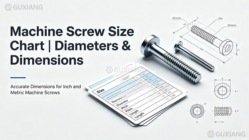
This comprehensive machine screw size chart provides decimal diameters, metric equivalents, nearest fractional sizes, and standard thread pitches for US machine screws from #0 through 1/2 inch. Use the interactive lookup tool below to quickly find complete dimensional data for any screw size, or browse the full reference table for engineering specifications.
Machine Screw Size Lookup Tool
Select a screw size from the dropdown to view its complete dimensional specifications including decimal diameter, metric equivalent, nearest fraction, and standard thread pitches.
Quick Size Lookup
Decimal Dia.
—
Metric (mm)
—
Nearest Fraction
—
TPI Coarse
—
TPI Fine
—
Pitch (mm)
—
Complete Machine Screw Diameter Table
The table below covers all standard US machine screw sizes from #0 to 1/2 inch. Numbered sizes (#0–#12) use the gauge system where the diameter equals 0.060" + (gauge number × 0.013"). Fractional sizes (1/4" and above) use direct inch measurements. Each entry includes the decimal diameter, metric equivalent, nearest standard fraction, and threads per inch (TPI) for both coarse (UNC) and fine (UNF) thread series.
Size
Decimal Dia. (in)
Metric (mm)
Nearest Fraction
TPI Coarse (UNC)
TPI Fine (UNF)
Coarse Pitch (mm)
Fine Pitch (mm)
Numbered Sizes (Gauge System)
#0
0.0600
1.52
1/16"
80
—
0.318
—
#1
0.0730
1.85
5/64"
64
72
0.397
0.353
#2
0.0860
2.18
3/32"
56
64
0.454
0.397
#3
0.0990
2.51
7/64"
48
56
0.529
0.454
#4
0.1120
2.84
7/64"
40
48
0.635
0.529
#5
0.1250
3.18
1/8"
40
44
0.635
0.577
#6
0.1380
3.51
9/64"
32
40
0.794
0.635
#8
0.1640
4.17
5/32"
32
36
0.794
0.706
#10
0.1900
4.83
3/16"
24
32
1.058
0.794
#12
0.2160
5.49
7/32"
24
28
1.058
0.907
Fractional Sizes (Direct Inch Measurement)
1/4"
0.2500
6.35
1/4"
20
28
1.270
0.907
5/16"
0.3125
7.94
5/16"
18
24
1.411
1.058
3/8"
0.3750
9.53
3/8"
16
24
1.588
1.058
7/16"
0.4375
11.11
7/16"
14
20
1.814
1.270
1/2"
0.5000
12.70
1/2"
13
20
1.954
1.270
Understanding Machine Screw Sizing
Machine screw sizes follow two distinct naming conventions depending on the diameter range. Understanding both systems is essential for proper fastener selection and cross-referencing between imperial and metric standards.
Numbered Sizes (#0–#12): The Gauge System
Numbered machine screw sizes use a gauge system where the nominal diameter in inches is calculated by the formula: Diameter = 0.060" + (gauge number × 0.013"). For example, a #10 screw has a nominal diameter of 0.060 + (10 × 0.013) = 0.190 inches. This system originated from the Birmingham Gauge (Stubs' Wire Gauge) used for wire diameter measurement. The most commonly used numbered sizes in general fastening applications are #4, #6, #8, #10, and #12.
Fractional Sizes (1/4"–1/2")
Sizes 1/4 inch and above are designated by their fractional inch diameter directly. These overlap with standard Unified Coarse Thread (UNC) and Unified Fine Thread (UNF) bolt sizes. At this range, machine screws share the same thread specifications as cap screws and hex bolts defined in ASME B1.1.
Common Machine Screw Head Types & Dimensions
Machine screws are available in numerous head configurations, each suited to different installation and aesthetic requirements. The table below shows typical head dimensions for the most common types across standard screw sizes.
⊕
Pan Head
Low-profile, rounded top with flat bearing surface. Most common for sheet metal and electrical applications. Head diameter approximately 1.9× nominal screw diameter.
◉
Round Head (Fillister)
High-domed head for decorative or high-clamp applications. Head height is taller than pan head, providing deeper drive recess and more material for cam-out resistance.
▽
Flat Head (Countersunk)
82° included angle for flush mounting. Head diameter approximately 1.9× nominal. Ideal when a smooth, flush surface is required after installation.
⬡
Hex Head
Six-sided head for wrench drive. Provides highest torque capability among machine screw heads. Common in structural and heavy-duty mechanical assemblies.
◎
Button Head (Socket)
Low-profile rounded head with hex socket drive. Offers a clean appearance with good torque capacity. Popular in machinery guards and enclosures.
▣
Truss Head
Wide, low-profile head with larger bearing surface. Used in sheet metal applications where pull-through is a concern. Head diameter approximately 2.3× nominal.
Machine Screw Standards Reference
Machine screw dimensions and thread specifications are governed by several key standards. Understanding which standard applies to your application ensures proper fit and performance.
ASME B1.1
Unified Thread Standard — defines the fundamental geometry for UNC, UNF, and UNEF thread series used in the US. Covers pitch diameter tolerances, thread class (1A/2A/3A for external, 1B/2B/3B for internal).
ASME B18.6.3
Mechanical Screws — covers dimensional requirements for machine screws of various head types including slotted, Phillips, and combination drive types in sizes #0 through 1 inch.
ASME B18.3
Socket Head Cap Screws — defines dimensions for socket head, socket button head, and socket flat head cap screws. Applies to sizes 1/4" and above but includes smaller metric equivalents.
ISO 12474 / ISO 7045
International metric equivalents — ISO 7045 (pan head), ISO 7046 (countersunk), ISO 7048 (cheese head). These provide metric cross-references for comparable imperial machine screw sizes.
How to Select the Right Machine Screw Size
Selection Checklist
Determine the clearance hole diameter — For a close fit, use the nominal screw diameter + 0.005"–0.010". For a free fit, add 0.015"–0.020". Refer to ANSI B27.5 for standard clearance hole tables.
Identify the thread series — UNC (coarse) is the default for general-purpose fastening; UNF (fine) provides better vibration resistance and finer tension adjustment. In thin materials, fine threads engage more reliably.
Calculate minimum thread engagement — For steel into steel, minimum engagement equals 1× nominal diameter. For aluminum or brass tapped holes, increase to 1.5×–2× nominal diameter to compensate for lower shear strength.
Check head type compatibility — Pan head for general use, flat head for flush surfaces, socket head for confined spaces requiring hex key drive, truss head for thin sheet metal where pull-through is a risk.
Verify material and plating — Standard machine screws are typically Case-carburized steel (self-tapping into metal) or stainless steel (corrosion resistance). Zinc plating provides basic protection; passivated stainless is preferred for outdoor or marine environments.
Machine Screw vs. Bolt: Key Differences
While often used interchangeably in casual conversation, machine screws and bolts have distinct definitions in fastener terminology. Machine screws are designed to thread directly into a tapped hole or nut, typically have smaller diameters (#0 through about 1/2"), and are tightened by turning the screw head. Bolts are intended for use with a nut, generally have larger diameters (1/4" and above), and are tightened by holding the bolt head stationary while turning the nut. The boundary between the two is not always sharp — a 1/4"-20 fastener can be classified as either a machine screw or a hex bolt depending on its length and intended installation method.
Frequently Asked Questions
What is the formula for machine screw gauge sizes?
The diameter of numbered machine screw sizes follows the formula: Diameter (inches) = 0.060 + (gauge number × 0.013). For example, a #8 screw has a nominal diameter of 0.060 + (8 × 0.013) = 0.164 inches. This formula applies to sizes #0 through #12. Sizes 1/4" and above use direct fractional inch designations instead of the gauge system.
What is the difference between UNC and UNF threads?
UNC (Unified National Coarse) threads have fewer threads per inch, making them faster to assemble and more resistant to cross-threading and galling. UNF (Unified National Fine) threads have more threads per inch, providing greater tensile stress area, better vibration resistance, and finer adjustment capability. For example, a 1/4" screw has 20 TPI in UNC but 28 TPI in UNF. Fine threads are preferred in thin-walled materials and precision instruments where small adjustments matter.
What size drill bit do I need for a machine screw clearance hole?
Clearance hole sizes depend on the fit class. For a close fit (free running), use a drill bit equal to the nominal screw diameter plus 0.005"–0.010". For a normal fit, add 0.015". For example, a #10 screw (0.190" nominal) needs a #11 drill (0.191") for close fit or a #7 drill (0.201") for normal fit. Standard clearance hole tables are published in ANSI B27.5 and most machinist handbooks.
How do I convert machine screw sizes to metric?
Multiply the decimal inch diameter by 25.4 to get millimeters. For example, a #10 screw at 0.190" equals 4.83 mm. However, metric machine screws use standardized diameters (M3, M4, M5, M6, etc.) that don't always match imperial sizes exactly. The nearest metric equivalents are: #4 ≈ M3 (2.84 vs 3.0 mm), #6 ≈ M3.5 (3.51 vs 3.5 mm), #8 ≈ M4 (4.17 vs 4.0 mm), #10 ≈ M5 (4.83 vs 5.0 mm), 1/4" ≈ M6 (6.35 vs 6.0 mm). Always verify thread pitch compatibility when substituting.
What is the most common machine screw size?
The most commonly used machine screw sizes in general-purpose applications are #6-32, #8-32, #10-24, and #10-32. In electronics and small appliances, #4-40 and #6-32 are extremely common. For heavier mechanical work, 1/4"-20 and 5/16"-18 are the go-to sizes. The #8-32 size is often considered the most versatile for general fabrication, offering a good balance of strength, availability, and ease of handling.
What does "10-32" mean on a machine screw?
The designation "10-32" breaks down as: "10" is the gauge size (nominal diameter = 0.060 + 10 × 0.013 = 0.190 inches) and "32" is the threads per inch (TPI), indicating a UNF (fine) thread series. If it said "10-24," the 24 would indicate a UNC (coarse) thread. For fractional sizes, the format is "1/4-20" meaning 1/4 inch diameter with 20 TPI (coarse thread).
How much thread engagement do I need for a machine screw?
A general rule of thumb: for steel tapped holes, minimum thread engagement should be at least 1.0× the nominal diameter. For cast iron, use 1.25×–1.5× diameter. For aluminum, brass, and other softer materials, use 1.5×–2.0× diameter. For example, a 1/4" screw in aluminum should engage at least 0.500" (2× diameter) of thread. Insufficient engagement is a common cause of thread stripping, especially in softer materials.
Can I use a metric screw in place of an imperial machine screw?
In some cases, yes — but with caution. Close-size substitutes like M3 for #4 or M5 for #10 may physically fit through clearance holes, but the thread pitches differ and should never be cross-threaded into an existing tapped hole. For through-bolt applications with a nut, metric substitutions are more forgiving. However, for critical or safety-related joints, always use the specified fastener. Mixing thread standards can lead to cross-threading, reduced clamping force, and joint failure.
What is the largest standard machine screw size?
The standard machine screw size range typically extends to 1/2 inch diameter (ASME B18.6.3). Above 1/2 inch, fasteners are generally classified as bolts or cap screws. However, some manufacturers produce machine screws up to 3/4 inch in special applications. In the metric system, machine screws commonly extend to M12 or M16. Beyond these sizes, hex head cap screws and structural bolts take over, governed by different standards (ASME B18.3 for socket head, ASME B18.2.1 for hex bolts).
What materials are machine screws typically made from?
The most common machine screw materials are: low-carbon steel (Grade 2, general purpose), medium-carbon steel (Grade 5, hardened and tempered for higher strength), alloy steel (Grade 8, heat-treated for the highest strength), 18-8 stainless steel (Type 304, corrosion resistant), 316 stainless steel (marine-grade corrosion resistance), brass (decorative and non-magnetic), and silicon bronze (marine applications). Material selection depends on the environment, required strength, and whether galvanic compatibility with the joined materials is a concern.
Disclaimer: The data provided in this machine screw size chart is for general reference purposes only. Dimensions and thread specifications may vary by manufacturer and applicable standards. Always verify critical dimensions against the original equipment manufacturer's specifications, ASME B1.1, ASME B18.6.3, or other applicable standards before procurement or installation. GUXIANG does not guarantee the accuracy or completeness of this data and assumes no liability for errors or omissions.
 ZH
ZH  EN
EN