





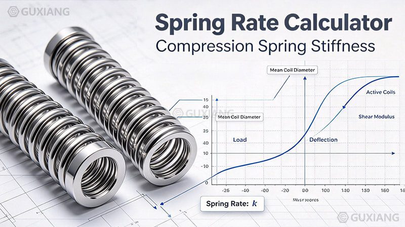
Calculate the spring rate of a compression spring in lb/in or N/mm from its wire diameter, mean coil diameter and active coils, or solve any two of force, deflection and spring rate. Results include spring index, solid height and a load-deflection chart you can read at a glance.
Spring Deflection Visualization
Drag the slider to compress the spring. The load required follows the straight line of a linear spring: force equals spring rate times deflection. Change the spring rate in the solver panel and watch the curve steepen or flatten.
What the diagram shows
- The coil pitch tightens as the spring compresses
- Force readout follows F = k × δ
- The load-deflection line is straight for a linear spring
- Compressing past solid height sets the spring permanently
Load-Deflection Chart
The chart plots force against deflection for the spring rate you entered. Because the relationship is linear, doubling the deflection doubles the required force.
Spring Dimensions Used in the Formula
Reading the dimensions
- d — wire diameter, raised to the 4th power
- D — mean coil diameter, raised to the 3rd power
- N — active coils only, in the denominator
- Lf — free length before any load
How to Calculate Spring Rate: Step by Step
Measure the wire diameter (d)
Measure the actual wire diameter with a micrometer, not the nominal bolt or shaft size. Even a small error is magnified four times in the formula.
Measure the outside diameter and subtract d
Mean coil diameter D equals outside diameter minus wire diameter. Use the mean coil diameter, not the OD, in the formula.
Count the active coils (N)
Total coils minus the inactive end coils. Closed and squared ends typically contribute 2 inactive coils, so a 10-coil spring has N = 8.
Apply k = G d4 / (8 D3 N)
Use the shear modulus for your material — 11.5 × 10⁶ psi for music wire and hard drawn, 11.2 × 10⁶ psi for oil tempered, 10.6 × 10⁶ psi for stainless 302.
Check the spring index
Divide D by d. Values between 4 and 12 are manufacturable; 6 to 9 is the preferred range. Outside that range the formula and the spring shop will both struggle.
Shear Modulus Reference
The shear modulus G is the only material property the spring rate formula needs. Values below are typical room-temperature figures; use the value from your material certificate for critical work.
| Material | Common Spec | Shear Modulus G (psi) | Shear Modulus G (GPa) | Typische Anwendung |
|---|
Spring Rate Reference Table
Rates for music wire compression springs with a 1.000 in mean coil diameter and 10 active coils. Thicker wire and larger coil counts move the rate up or down along the curve shown above.
Unit Conversions
Spring Rate
1 lb/in = 0.175127 N/mm. 1 N/mm = 5.710149 lb/in. A 100 lb/in spring is 17.51 N/mm, and a 20 N/mm spring is 114.20 lb/in.
Force
1 lbf = 4.448222 N. 1 N = 0.224809 lbf. A 50 lbf preload is 222.41 N, and a 500 N load is 112.40 lbf.
Deflection
1 in = 25.4 mm. 1 mm = 0.039370 in. Two inches of travel is 50.8 mm, and 25 mm of travel is 0.984 in.
Wire & Coil Diameter
Convert with the same 25.4 factor: a 0.192 in wire is 4.877 mm, a 12.7 mm mean coil is 0.500 in. Always convert dimensions before applying the rate formula.
Spring Rate Design Tips
Bewährte Verfahren
- Keep the spring index C = D/d between 4 and 12, ideally 6 to 9
- Never specify compression to solid height in service — target 15-20% of free length of working travel maximum
- Raising wire diameter one gauge can more than double the spring rate
- Adding active coils lowers the rate roughly in proportion
- Check stress, not just rate, when the deflection is large — rate alone does not guarantee the spring will survive
- Shot peening and preset remove set, they do not change the spring rate
- Compensate for temperature: shear modulus drops as temperature rises, lowering the rate
- Verify the rate on a load tester after coiling — the formula is a starting point, not a guarantee
Häufig gestellte Fragen
Spring rate (k) is the force required to compress or extend a spring by a unit distance, expressed in lb/in or N/mm. A rate of 100 lb/in means 100 pounds of force compresses the spring one inch. Spring rate is a constant for a linear compression spring over its working range.
Verwendung k = G d^4 / (8 D^3 N), where G is the shear modulus of the material, d is the wire diameter, D is the mean coil diameter, and N is the number of active coils. The wire diameter is raised to the fourth power and the mean coil diameter to the third, so small changes in either dimension produce large changes in spring rate.
Spring index C is the ratio of mean coil diameter to wire diameter, C = D/d. An index between 4 and 12 is considered manufacturable, with 6 to 9 preferred. Below 4 the wire is difficult to coil and stress is very high; above 12 the spring tends to buckle and the rate formula becomes less accurate.
Multiply lb/in by 0.175126835 to get N/mm. For example, a 200 lb/in spring equals about 35.03 N/mm. To convert the other way, multiply N/mm by 5.710148617.
Common values are approximately 11.5 × 10⁶ psi (79.3 GPa) for music wire and hard drawn wire, 11.2 × 10⁶ psi (77.2 GPa) for oil tempered wire, 11.6 × 10⁶ psi (80 GPa) for chrome silicon, 10.6 × 10⁶ psi (73 GPa) for stainless 302, and 6.2 × 10⁶ psi (42.7 GPa) for phosphor bronze.
Total coils includes the inactive end coils that touch the adjacent coil and do not contribute to deflection. Active coils N is total coils minus the inactive end coils, typically 2 for closed and squared ends. Only active coils are used in the spring rate formula.
Verwendung F = k x, where F is force, k is spring rate and x is deflection. For a 150 lb/in spring compressed 0.5 inch, the force is 75 lb. The calculator's force-deflection solver performs this calculation in either direction.
Solid height is the length of the spring when all coils are touching, calculated as total coils times wire diameter. A compression spring must never be compressed to solid height in service because stress rises sharply and the spring takes a permanent set. Always leave working travel below solid height.