 ZH
ZH  EN
EN 

Our compression spring range covers closed and ground end, closed unground end, open end, open and ground end, cylindrical, conical, barrel, variable pitch, die spring, rectangular wire, heavy load and micro compression springs manufactured to ISO 10243, DIN 2098 and EN 13906. Available in music wire, stainless steel 302/316 and chrome silicon alloy for engineers and industrial buyers.
Filter By
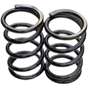
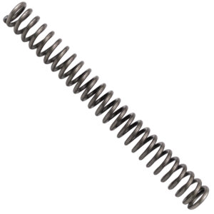
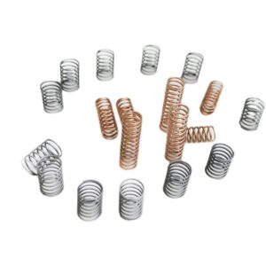
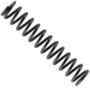

A compression spring is an open-coil helical spring that resists axial compressive force. When a load pushes the coils together, the spring stores mechanical energy by twisting the wire in torsion along the helix and compressing the coils closer to one another. When the load is removed, the spring returns to its free length, releasing the stored energy. This simple mechanism—wire wound into a helix with spacing between coils—underpins everything from automotive suspension to medical syringes.
Compression springs are the most widely used spring type in industrial design. They appear wherever a force must be absorbed, a component must return to its starting position, or two parts must be held apart under load. Shock absorbers, valve return springs, battery contacts, stamping die strippers, and push-button mechanisms all rely on the compression spring’s ability to deliver repeatable, predictable force over millions of cycles.
A compression spring converts work done by an external force into strain energy stored in the wire. As the spring compresses, each cross-section of wire experiences torsional shear stress—the helix angle means the applied axial load translates into a twisting moment on the wire. The spring rate, measured in N/mm or lb/in, defines how much force is required per unit of deflection. A linear spring maintains the same rate throughout its travel; a variable-rate spring stiffens as it compresses.
The spring’s physical limits are defined by three critical heights: free length (no load), solid height (all coils touching), and the working range between them. The usable travel of a compression spring is typically 30–40% of the distance from free length to solid height—pushing beyond this risks coil clash, buckling, and permanent set. For springs with a slenderness ratio (free length ÷ mean diameter) above 4, buckling becomes the dominant failure mode, and the spring must either be guided on a rod or sleeved in a bore.
End condition governs how the spring sits against its mating surfaces and how the load is introduced. A ground end creates a flat bearing surface perpendicular to the spring axis; an unground end is simply cut square, leaving an open coil that contacts the seat at a single point. The end type affects free length tolerance, solid height, and how evenly stress distributes through the first active coil.
Compression springs are classified first by end treatment, then by coil geometry, and finally by the performance regime they target. These three layers of classification intersect—a die spring, for example, is always closed and ground, cylindrical in geometry, and built for high-load short-stroke cycling.
End types determine how the spring interfaces with its housing. The closed and ground end is the standard for precision applications: the final coil is wound flat against the adjacent coil and the tip is ground square to the axis, creating a flat seat that distributes the load evenly and keeps the spring standing straight. Closed unground end winds the final coil flat but skips the grinding operation—the tip remains as-wound. This saves cost where seating precision is relaxed. An open end is simply cut—the last coil remains at its helix pitch, touching the seat at just one point. This is the cheapest option and is used where the spring is guided on a rod or in a bore and seating alignment is not critical. Open and ground end is a middle ground: the coil stays open but the tip is ground flat to improve seating.
Geometric types move beyond the standard cylinder. A conical spring tapers from a larger diameter at one end to a smaller diameter at the other. As it compresses, the larger-diameter coils collapse to solid height first, nesting inside each other progressively—this allows the solid height to equal roughly one wire diameter, far shorter than a cylindrical spring of the same free length. A barrel or hourglass spring has a larger diameter at mid-length than at the ends, reducing the lateral space it sweeps during compression and lowering the risk of contact with surrounding components. A variable pitch spring spaces its coils unevenly along the length—the closely pitched coils compress to solid first, increasing the overall spring rate as travel progresses. This is the standard solution for vibration-sensitive applications where a single natural frequency would cause resonance.
High-performance types are engineered for extreme duty cycles, impact loads, or space constraints. Die springs follow ISO 10243 with rectangular or round wire in chrome silicon or chrome vanadium alloy, heat-treated to HRC 47–51, and color-coded by load rating. Rectangular wire springs pack more material into the same envelope than round wire, increasing the force output per unit of deflection for the same outer diameter. Heavy load springs use oversized wire diameters and tighter coil spacing for applications like railway buffers, heavy press tooling, and industrial shock absorption where deflection is small but force is measured in tonnes.
Micro and miniature springs operate at the other end of the scale—wire diameters from 0.08 mm, free lengths under 5 mm—used in medical devices, microswitches, and instrumentation where the spring itself may be barely visible to the naked eye.
The twelve types below span the four classification groups: end finish, geometry, high performance, and specialty. The end type is a specification applied to any of the geometric types—so a conical spring may be ordered with closed and ground ends, and a cylindrical die spring always is.
| Type | Group | Defining Feature | Key Standard | Typical Application |
|---|---|---|---|---|
| Closed & Ground End | End Finish | Final coil wound flat and tip ground square for level seating | ISO 10243 | Precision mechanisms, valve springs, die springs, aerospace |
| Closed Unground End | End Finish | Final coil wound flat, tip left as-cut | — | General industrial, guided springs, cost-sensitive production |
| Open End | End Finish | Final coil stays at helix pitch, tip cut square | — | Springs guided on rod or bore, low-precision seating |
| Open & Ground End | End Finish | Coil at helix pitch but tip ground flat | — | Mid-range precision where closed winding is not required |
| Cylindrical | Geometry | Constant diameter and pitch, linear spring rate | DIN 2098 | Universal default—automotive, machinery, consumer products |
| Conical | Geometry | Tapered diameter, progressive nesting to ≈1 wire diameter solid height | — | Compact assemblies, automotive strut inserts, telescoping guides |
| Barrel / Hourglass | Geometry | Larger mid-diameter, reduced lateral sweep during compression | — | Confined bores, surrounding-component clearance, lateral stability |
| Variable Pitch | Geometry | Uneven coil spacing, progressive spring rate that stiffens with travel | — | Vibration isolation, engine valve springs, resonance avoidance |
| Die Spring | Performance | Rectangular/round wire, chrome alloy, HRC 47–51, color-coded load rating | ISO 10243 | Stamping dies, press tooling, high-cycle short-stroke applications |
| Rectangular Wire | Performance | Rectangular section wire packs more force into same OD | — | Heavy press tooling, clutch springs, high-force compact envelopes |
| Heavy Load | Performance | Oversized wire, tight pitch, forces measured in tonnes | — | Railway buffers, industrial shock absorbers, bridge bearings |
| Micro / Miniature | Specialty | Wire Ø 0.08–1.0 mm, free length under 5 mm | — | Medical devices, microswitches, instrumentation, watch mechanisms |
Music Wire (ASTM A228)
High-carbon steel, cold-drawn to high tensile strength—the standard material for general-purpose compression springs
Tensile range 1,600–2,400 MPa depending on wire diameter; maximum operating temperature 120 °C
Excellent fatigue resistance at moderate temperatures; prone to stress corrosion in wet environments unless plated
Stainless Steel 302/304 (ASTM A313)
Corrosion-resistant, non-magnetic after cold working; operating temperature range −200 °C to 290 °C
Lower tensile strength than music wire at the same diameter—spring rate must be compensated by larger wire or more coils
Preferred for food processing, marine, medical, and outdoor equipment
Stainless Steel 316
Molybdenum addition for pitting resistance in chloride environments: coastal, offshore, chemical processing
Slightly lower strength than 302 at the same wire diameter
Chrome Silicon (ASTM A401, AISI 9254)
Alloy steel with superior fatigue life under high stress: standard for die springs, valve springs, and cyclic-load applications
Operating temperature up to 250 °C; quenched and tempered to HRC 47–51
Color-coded by ISO 10243 load rating: green (light), blue (medium), red (heavy), yellow (extra heavy)
Chrome Vanadium (ASTM A231, AISI 6150)
Good fatigue properties at moderate cost; temperature range up to 220 °C
Common in heavy equipment, agricultural machinery, and railway suspension
Inconel / Nimonic Alloys
Nickel-based superalloys for temperatures up to 450 °C and corrosive environments
Specified for turbine seals, downhole oil tools, and exhaust systems where stainless steel would anneal and lose spring force
Step 1: Load and deflection—what force at what travel?
Define the force required at two positions: installed (preloaded) height and working height. The difference between these divided by the travel distance defines the required spring rate. If the spring must deliver constant force, choose a cylindrical linear-rate design with the rate as calculated. If the spring must stiffen as it compresses—to avoid a resonance frequency or to deliver progressive resistance—choose a conical or variable pitch design.
Step 2: Envelope constraints—how much space is there?
Measure the maximum outer diameter of the bore or the minimum inner diameter of any guide rod. A spring should have 0.5–1.0 mm radial clearance to the bore wall to allow for diameter expansion during compression (up to 5% of mean diameter). The solid height must be less than the minimum compressed height of the assembly. If solid height exceeds available space, switch to a conical spring—its nesting coils collapse to roughly one wire diameter.
Step 3: Environment and cycle life
For more than 10⁶ cycles or alternating loads, specify chrome silicon or chrome vanadium alloy and demand closed and ground ends to distribute stress evenly through the end coils. For corrosive environments, move to stainless steel 302 or 316 and apply a 20% derating factor to published fatigue limits. For temperatures exceeding 120 °C, music wire and standard stainless grades are out—select chrome silicon (to 250 °C) or Inconel (to 450 °C).
What is the difference between a compression spring and an extension spring? Compression springs push back against a load that squeezes them shorter; extension springs pull back against a load that stretches them longer. Compression springs have space between coils at free length; extension springs have coils touching with hooks or loops at the ends.
How do I calculate the spring rate of a compression spring? Spring rate k = Gd⁴/(8D³n), where G is shear modulus, d is wire diameter, D is mean coil diameter, and n is active coils. Most manufacturers quote rate tolerances of ±5–10%.
Why does a compression spring buckle? A spring buckles when its slenderness ratio (free length ÷ mean coil diameter) exceeds 4 and no guide rod or bore constrains it laterally. At the critical compression ratio, the spring collapses sideways. The fix is a guide rod, a bore sleeve, or a barrel spring shape.
What does “closed and ground” mean on a compression spring? The final coil at each end is wound flat against the adjacent coil (closed), and the wire tip is machined flat and perpendicular to the spring axis (ground). This creates a full bearing surface for even load distribution and upright stability.
Can compression springs be stacked in series? Yes—two springs placed end to end in series halve the effective spring rate (1/k_total = 1/k₁ + 1/k₂) while doubling the available travel. The springs must be separated by a flat washer to prevent inter-coil entanglement.
How many cycles can a compression spring withstand? A properly designed spring in music wire with stress below the endurance limit can reach 10⁷ cycles. Die springs in chrome silicon are rated for 10⁶ cycles at 30% deflection. Beyond these limits, the spring will take a permanent set or fracture from fatigue.
Social Chat is free, download and try it now here!